- 您现在的位置:买卖IC网 > Sheet目录530 > UPC8182TB-E3-A (CEL)IC MMIC AMP 6-SUPER MINIMOLD
�� �
�
�?� PC8182TB�
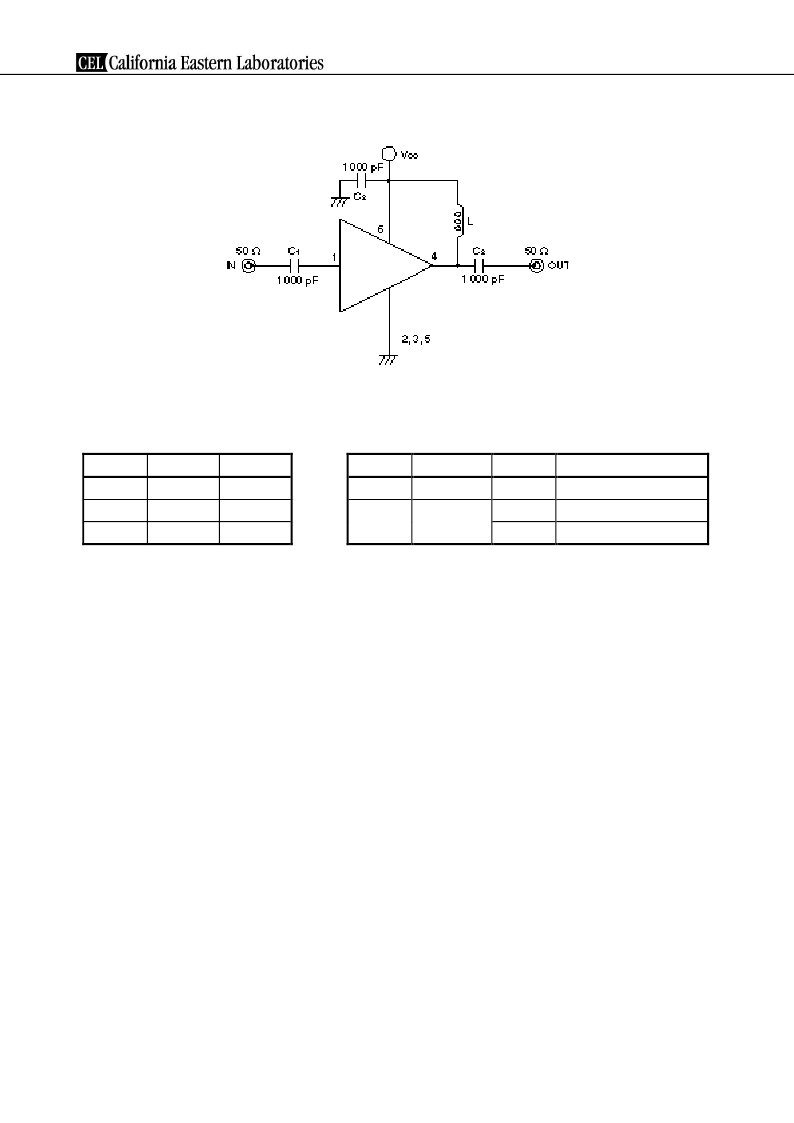
�TEST� CIRCUITS�
�COMPONENTS� OF� TEST� CIRCUIT�
�FOR� MEASURING� ELECTRICAL�
�CHARACTERISTICS�
�EXAMPLE� OF� ACTUAL� APPLICATION� COMPONENTS�
�Type�
�Value�
�Type�
�Value�
�Operating� Frequency�
�C� 1� ,� C� 2�
�C� 3�
�L�
�Bias� Tee�
�Capacitor�
�Bias� Tee�
�1� 000� pF�
�1� 000� pF�
�1� 000� nH�
�C� 1� to� C� 3�
�L�
�Chip� capacitor�
�Chip� inductor�
�1� 000� pF�
�100� nH�
�10� nH�
�100� MHz� or� higher�
�100� MHz� or� higher�
�2.0� GHz� or� higher�
�INDUCTOR� FOR� THE� OUTPUT� PIN�
�The� internal� output� transistor� of� this� IC� consumes� 20� mA,� to� output� medium� power.� To� supply� current� for� output�
�transistor,� connect� an� inductor� between� the� Vcc� pin� (pin� 6)� and� output� pin� (pin� 4).� Select� large� value� inductance,� as�
�listed� above.�
�The� inductor� has� both� DC� and� AC� effects.� In� terms� of� DC,� the� inductor� biases� the� output� transistor� with� minimum�
�voltage� drop� to� output� enable� high� level.� In� terms� of� AC,� the� inductor� makes� output-port-impedance� higher� to� get�
�enough� gain.� In� this� case,� large� inductance� and� Q� is� suitable.�
�For� above� reason,� select� an� inductance� of� 100� ?� or� over� impedance� in� the� operating� frequency.� The� gain� is� a�
�peak� in� the� operating� frequency� band,� and� suppressed� at� lower� frequencies.�
�The� recommendable� inductance� can� be� chosen� from� example� of� actual� application� components� list� as� shown�
�above.�
�CAPACITORS� FOR� THE� VCC,� INPUT,� AND� OUTPUT� PINS�
�Capacitors� of� 1� 000� pF� are� recommendable� as� the� bypass� capacitor� for� the� Vcc� pin� and� the� coupling� capacitors�
�for� the� input� and� output� pins.�
�The� bypass� capacitor� connected� to� the� Vcc� pin� is� used� to� minimize� ground� impedance� of� Vcc� pin.� So,� stable� bias�
�can� be� supplied� against� Vcc� fluctuation.�
�The� coupling� capacitors,� connected� to� the� input� and� output� pins,� are� used� to� cut� the� DC� and� minimize� RF� serial�
�impedance.� Their� capacitance� are� therefore� selected� as� lower� impedance� against� a� 50� ?� load.� The� capacitors� thus�
�perform� as� high� pass� filters,� suppressing� low� frequencies� to� DC.�
�To� obtain� a� flat� gain� from� 100� MHz� upwards,� 1� 000� pF� capacitors� are� used� in� the� test� circuit.� In� the� case� of� under�
�10� MHz� operation,� increase� the� value� of� coupling� capacitor� such� as� 10� 000� pF.� Because� the� coupling� capacitors� are�
�determined� by� equation,� C� =� 1/(2� ?� Rfc).�
�Data� Sheet� PU10206EJ01V0DS�
�7�
�发布紧急采购,3分钟左右您将得到回复。
相关PDF资料
UPC8187TB-EV24
EVAL BOARD UPC8187TB 2.4GHZ
UPC8190K-EVAL
EVAL BOARD FOR UPC8190K
UPC8191K-E1-A
IC I/Q MODULATOR AGC 20-QFN
UPC8194K-EVAL
EVAL BOARD FOR UPC8194K
UPC8195K-E1-A
IC I/Q MODULATOR AGC 20-QFN
UPC8204TK-EV24
EVAL BOARD UPC8204TK 2.4GHZ
UPC8211TK-EV24
EVAL BOARD UPC8211TK 2.4GHZ
UPC8215TU-A
IC AMP LOW NOISE 8-MINIMOLD
相关代理商/技术参数
UPC8182TB-E3-AZ
制造商:NEC 制造商全称:NEC 功能描述:3 V, 2.9 GHz SILICON MMIC MEDIUM OUTPUT POWER AMPLIFIER FOR MOBILE COMMUNICATIONS
UPC8182TB-EVAL
功能描述:放大器 IC 开发工具 For UPC8182TB-A RoHS:否 制造商:International Rectifier 产品:Demonstration Boards 类型:Power Amplifiers 工具用于评估:IR4302 工作电源电压:13 V to 23 V
UPC8186K-E1
制造商:未知厂家 制造商全称:未知厂家 功能描述:RF MODULATOR|BIPOLAR|LLCC|24PIN|PLASTIC
UPC8187TB
功能描述:上下转换器 RFIC Freq Upconvertr RoHS:否 制造商:Texas Instruments 产品:Down Converters 射频:52 MHz to 78 MHz 中频:300 MHz LO频率: 功率增益: P1dB: 工作电源电压:1.8 V, 3.3 V 工作电源电流:120 mA 最大功率耗散:1 W 最大工作温度:+ 85 C 安装风格:SMD/SMT 封装 / 箱体:PQFP-128
UPC8187TB-A
功能描述:上下转换器 RFIC Freq Upconvertr RoHS:否 制造商:Texas Instruments 产品:Down Converters 射频:52 MHz to 78 MHz 中频:300 MHz LO频率: 功率增益: P1dB: 工作电源电压:1.8 V, 3.3 V 工作电源电流:120 mA 最大功率耗散:1 W 最大工作温度:+ 85 C 安装风格:SMD/SMT 封装 / 箱体:PQFP-128
UPC8187TB-E3
制造商:California Eastern Laboratories (CEL) 功能描述:Frequency Up-Converter For Wireless Transceiver 6-Pin SOT-363 T/R
UPC8187TB-E3-A
功能描述:上下转换器 RFIC Freq Upconvertr RoHS:否 制造商:Texas Instruments 产品:Down Converters 射频:52 MHz to 78 MHz 中频:300 MHz LO频率: 功率增益: P1dB: 工作电源电压:1.8 V, 3.3 V 工作电源电流:120 mA 最大功率耗散:1 W 最大工作温度:+ 85 C 安装风格:SMD/SMT 封装 / 箱体:PQFP-128
UPC8187TB-EV08
功能描述:射频开发工具 for UPC8187TB-A at 800 MHz RoHS:否 制造商:Taiyo Yuden 产品:Wireless Modules 类型:Wireless Audio 工具用于评估:WYSAAVDX7 频率: 工作电源电压:3.4 V to 5.5 V